Structural · NP-001
Footscray Pedestrian Overpass
Final conceptual design of the steel deck framing, lift support frames and pad footings for an 82 m covered footbridge over a live railway. Every member was checked to AS 4100 by hand, then verified in SPACE GASS.
01 · The brief
A covered crossing over four live platforms
The Footscray Pedestrian Overpass gives pedestrians and cyclists a sheltered crossing over the four active platforms at Footscray station in Melbourne, with stairs and lifts down to the platforms. It was the SEJ201 project for the unit’s client scenario, the City of Maribyrnong.
My five-person team (Team 33) wrote the group design brief, which averaged 85%, a High Distinction. My part of it was the pad footing analysis. This final report was individual: I took the deck crossbeams, main girders, lift support frame and lift footing to a final conceptual design, checked to AS 4100 and verified in SPACE GASS, with drawings a tenderer could price from.
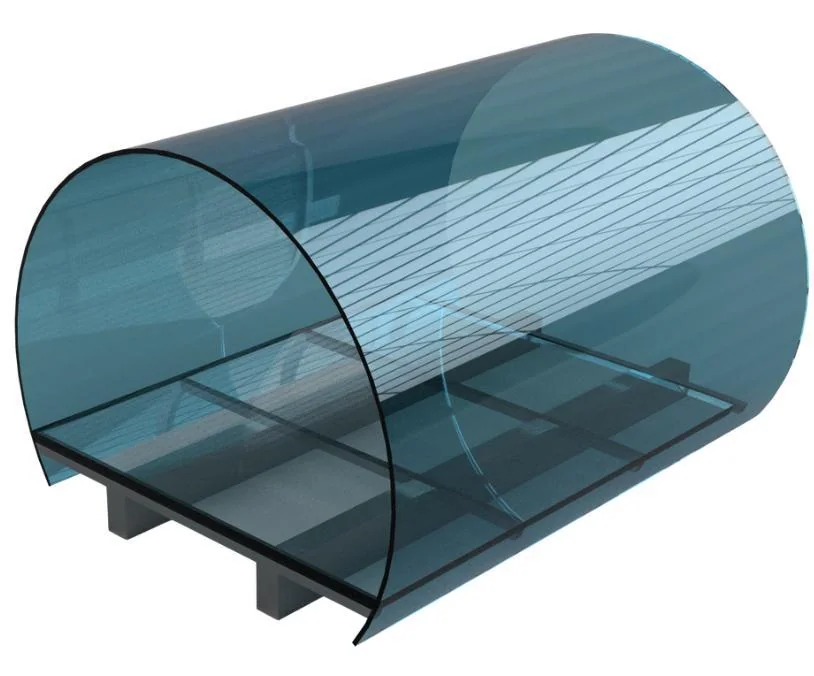
The geometry: an 82 m bridge on five piers (four 20.5 m spans). A 165 mm in-situ concrete deck sits on 6.6 m crossbeams with 1.8 m overhangs, carried by two continuous welded-beam girders 3 m apart, under a curved canopy. At the landings, a pair of 3 × 3 × 12 m square-hollow-section frames carry the lift shafts, each on a shallow pad footing in stiff clay.
02 · Week 7
Two new constraints changed everything
In week 7, two new constraints were added to the project. Either would have changed the design on its own. Together they turned the lift structure from a side item into the critical part of the job.
Constraint 1 · Geotechnical
180 100 kPa
Lower allowable bearing pressure
With the unit’s minimum factor of safety of 3.0 on bearing, that leaves 33.3 kPa of usable pressure under the footing.
Constraint 2 · AS 5100.2
500 kN
Rail collision load
Any component within 10 m of a track must resist a 500 kN ultimate lateral load, applied anywhere on it and not combined with wind. I checked it for strength (LC102) and stability (LC140).
I also fixed the errors the marker found in our brief: lift moving parts treated as a live load, all truss loads applied at nodes, wind combined with gravity, footing actions taken from the frame reactions (including the moment we’d missed), pattern live loading on the continuous girders, and the true 2.5625 m crossbeam spacing instead of the 2.8 m maximum.
03 · Result
The adopted design
The deck is governed by the original Basis of Design: deflection and pattern loading. The lift frame and footing are governed by the new constraints. Every member group sits between 0.80 and 0.91 utilisation, and the next lighter section in each group fails.
≈55.5t
Structural steel
133m³
Footing concrete (both lift footings)
33
360UB44.7 crossbeams at 2.5625 m
1000WB215
Continuous main girders
| Element and section | Governing check | Demand / capacity | Utilisation |
|---|---|---|---|
| Deck crossbeams360UB44.7 Gr 300PLUS | Cantilever tip deflection (LC052) | 4.28 mm / 5.0 mm | 0.86 |
| Main girders1000WB215 Gr 300 | Hogging at pier P2 (LC101, pattern) | 2,074 kNm / 2,583 kNm | 0.80 |
| Lift frame columns200×200×8.0 SHS C450L0 | Compression, base tier (LC102) | 2,024 kN / 2,230 kN | 0.91 |
| Lift frame diagonals200×200×6.0 SHS C450L0 | Compression, top diagonal (LC102) | 972 kN / 1,086 kN | 0.90 |
| Lift frame ties125×125×4.0 SHS C450L0 | Compression (LC102) | 500 kN / 557 kN | 0.90 |
| Lift pad footing10.5 m square, founded 1.3 m | Bearing pressure, FoS ≥ 3.0 (service) | 33.26 kPa / 33.33 kPa | FoS 3.01 |
04 · Lift support frame
The collision load governs every lateral member
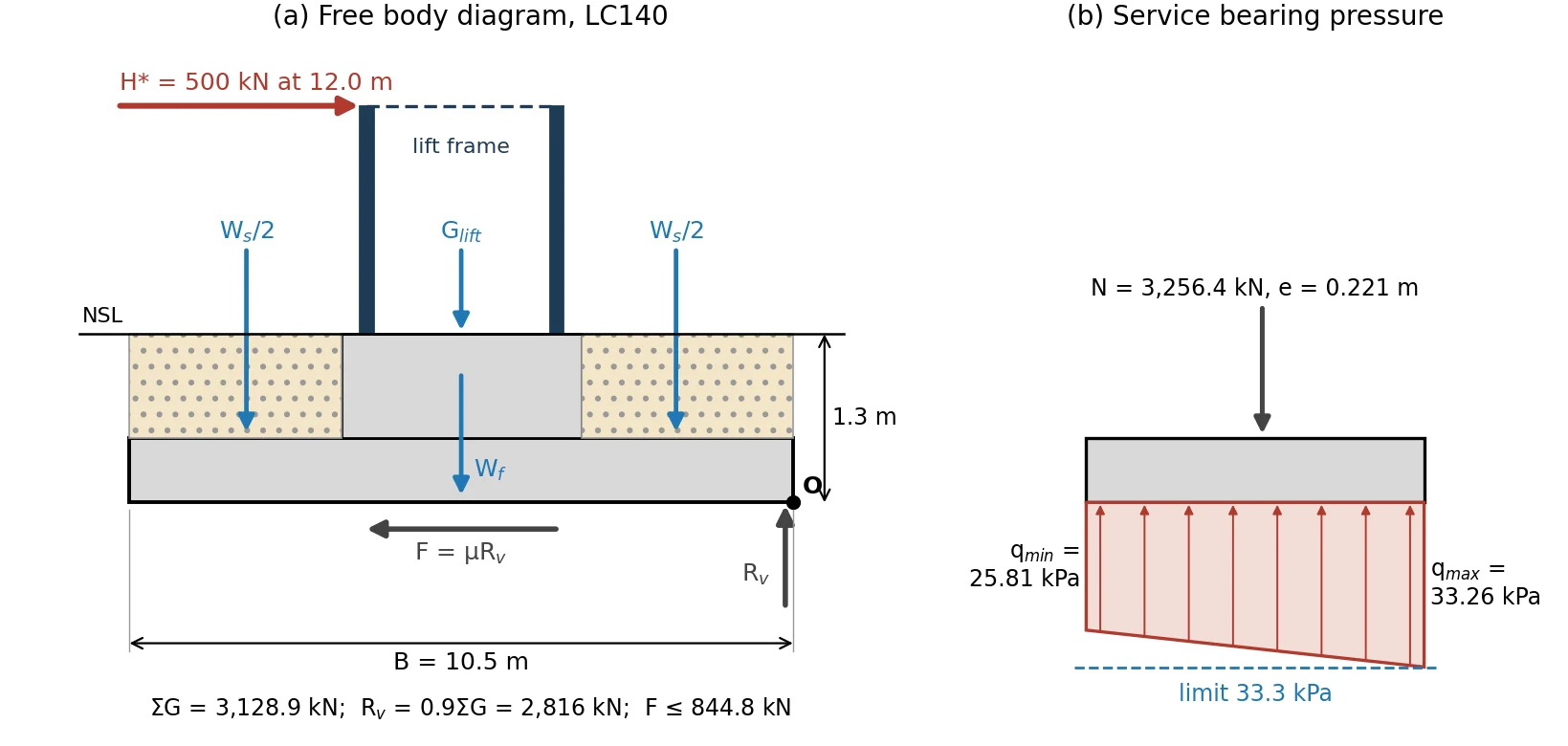
The collision force is 4.15 times the total ultimate wind force on the lift shaft, and it can act at the top of the 12 m frame, while the wind resultant sits at mid-height. At the underside of the footing that’s 6,650 kNm of overturning against 880 kNm for wind.
With the load at the top node, every tie above the base carries the full 500 kN (the base tie is a zero-force member, because B sits on a roller), each diagonal carries 500 / cos θ, and the columns pick up the overturning couple, growing from 840 kN in the top tier to 2,024 kN at the base. Reverse the load and every tie and diagonal flips sign, so they’re designed for the same force in compression.
Under wind alone, 100 × 100 SHS would have done the job. The collision case takes the frame to 200 × 200 SHS columns and diagonals and 125 × 125 ties, all working at 0.90–0.91.
I flagged the top-node position as an assumption to revisit: a derailed train would hit near rail level. With the load at 2.5 m, the base column force drops to about 440 kN. That, and adding plan bracing so two faces share the load, are the first things I’d confirm at detailed design.
05 · Lift pad footing
Why the footing grew from 4.8 m to 10.5 m
Bearing ended up controlling, not collision. The concrete and backfill alone put about 27 kPa on the clay, which leaves roughly 6 kPa of the 33.3 kPa limit for the lift loads and the wind moment, so each extra metre of width buys very little.
The 4.8 m footing from our design brief fails the revised bearing check on its own (FoS 1.28), before collision is even considered. 10.5 m is the smallest square that passes everything. Drag the slider to see why. It runs the same equations as the report.
Interactive · reproduces the report’s footing checks
Resize the lift footing
Width Bm
- Bearing pressure3.01 ≥ 3.0Service G + Q + Wp vs 100 kPa allowable
- Overturning (collision)2.22 ≥ 1.5LC140: 0.9G + 500 kN at 12 m
- Sliding (collision)1.69 ≥ 1.5Friction only, μ = 0.3
- Stability (wind)7.00 ≥ 1.5LC120: worse of overturning and sliding
Passes every check; bearing governs at FoS 3.01.
- Peak bearing pressure
- 33.3 of 33.3 kPa
- Concrete per footing
- 66.7 m³
- Excavation per footing
- 143 m³
A compliant answer isn’t automatically a good one
A 10.5 m pad beside live platforms needs a 143 m³ excavation per lift and requires the lift centre to sit at least 9.25 m from the nearest track. The drawings didn’t show track positions, so I listed that clearance as the key risk.
I put two alternatives forward. If the 100 kPa limit can be used directly rather than divided by the factor of safety, collision stability governs instead and an 8.4 × 8.4 × 1.6 m mass-concrete block works. Where platform space is tight, four bored piers under a pile cap would resist the uplift and lateral load in a footprint close to the original. That’s the option I’d ask tenderers to price.
06 · Crossbeams & girders
The deck: deflection and pattern loading
Crossbeam · 360UB44.7 Gr 300PLUS
Hogging along its full length
The 1.8 m overhangs balance the 3 m back-span, so the crossbeam hogs even at mid-span. Its unrestrained bottom flange is in compression, which makes lateral–torsional buckling the strength check (88.7 kNm vs φMb = 132.9 kNm).
Deflection governs, though: the 20 kN point load at the tip gives 4.28 mm against a 5.0 mm limit. The lighter 310UB40.4 passes strength but deflects 6.0 mm.
Main girder · 1000WB215 Gr 300
Load every pattern, not every span
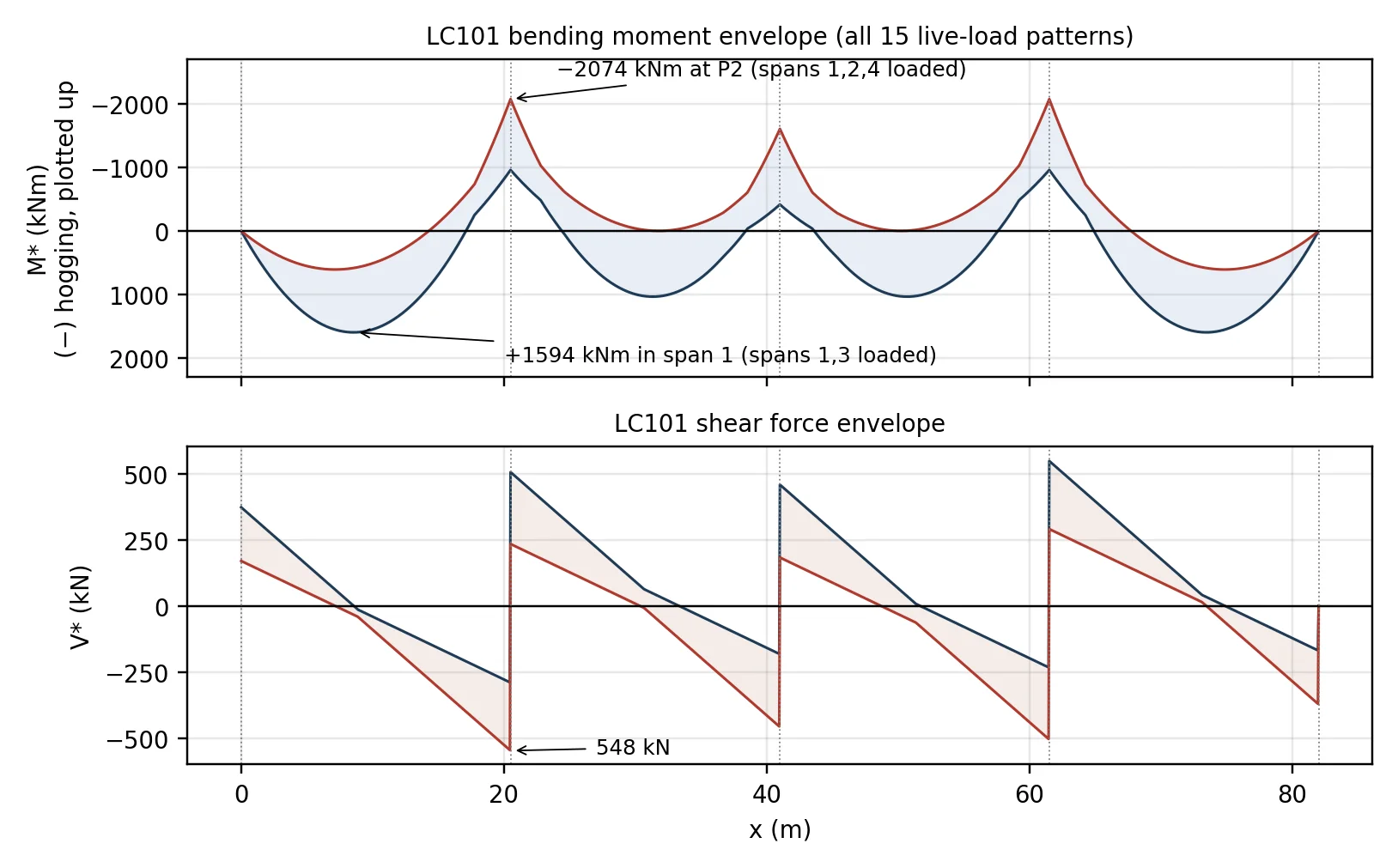
Loading all four spans, which is what our brief did, doesn’t give the worst case for a continuous beam. I ran all 15 combinations of loaded spans: spans 1, 2 and 4 loaded give the peak hogging at pier P2, 2,074 kNm, 6% above the all-spans case.
That matters: the next lighter 900WB175 falls 2% short once pattern loading is in, but would have “passed” the old way.
07 · Verification
Checked twice: hand calcs vs SPACE GASS
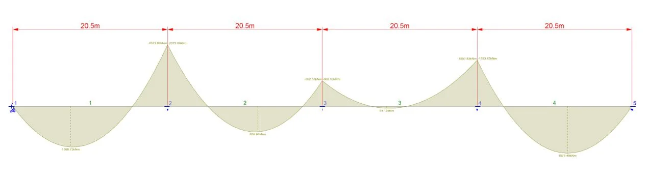
Each steel element was rebuilt as a SPACE GASS model: a 2D crossbeam, a four-span girder with each span’s live load as its own case, and a pin-jointed plane truss for the lift frame. The largest difference in the comparison tables is 0.15%, on the girder deflection (LC051). By hand I added the dead- and live-load peaks even though they fall at slightly different points along the span, while SPACE GASS reports the deflection at fixed output points.
| Result | Hand calc | SPACE GASS | Difference |
|---|---|---|---|
| Crossbeam: moment at support B | −88.70 kNm | −88.69 kNm | 0.01% |
| Crossbeam: tip deflection, LC052 | 4.28 mm | 4.28 mm | 0.00% |
| Girder: hogging at P2, spans 1, 2, 4 loaded | −2,073.7 kNm | −2,073.9 kNm | 0.01% |
| Girder: max sagging, spans 1, 3 loaded | +1,593.8 kNm | +1,594.0 kNm | 0.01% |
| Girder: max deflection, LC051 | 44.54 mm | 44.47 mm | 0.15% |
| Lift frame: base column C4, LC102 | −2,024.2 kN | −2,024.2 kN | 0.00% |
| Lift frame: top diagonal D3, LC102 | +971.8 kN | +971.8 kN | 0.00% |
08 · Deliverable
Drawings for tender
Five A3 sheets with member sizes, grades, numbers and set-out, plus provisional connection, bracing and stiffener items so a tenderer can allow for them. Click to open full size.
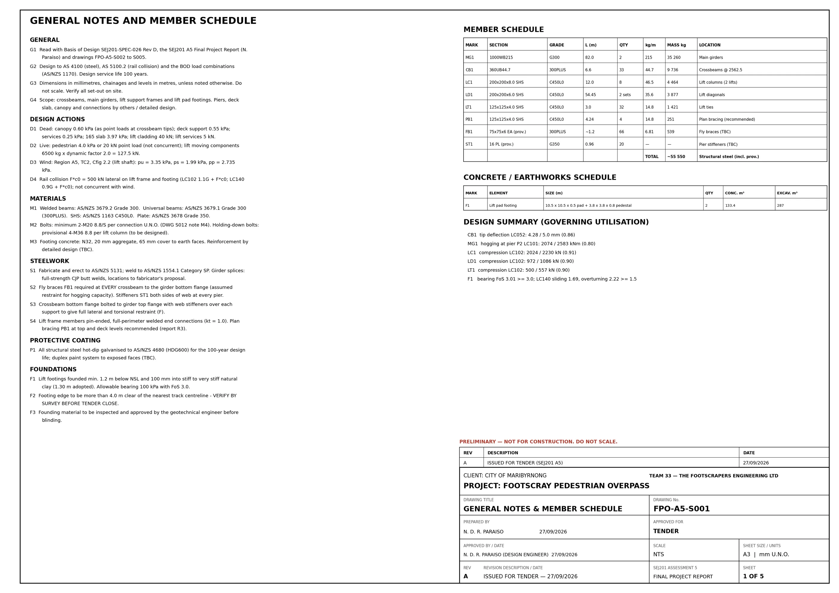
S001 — General notes & member schedule 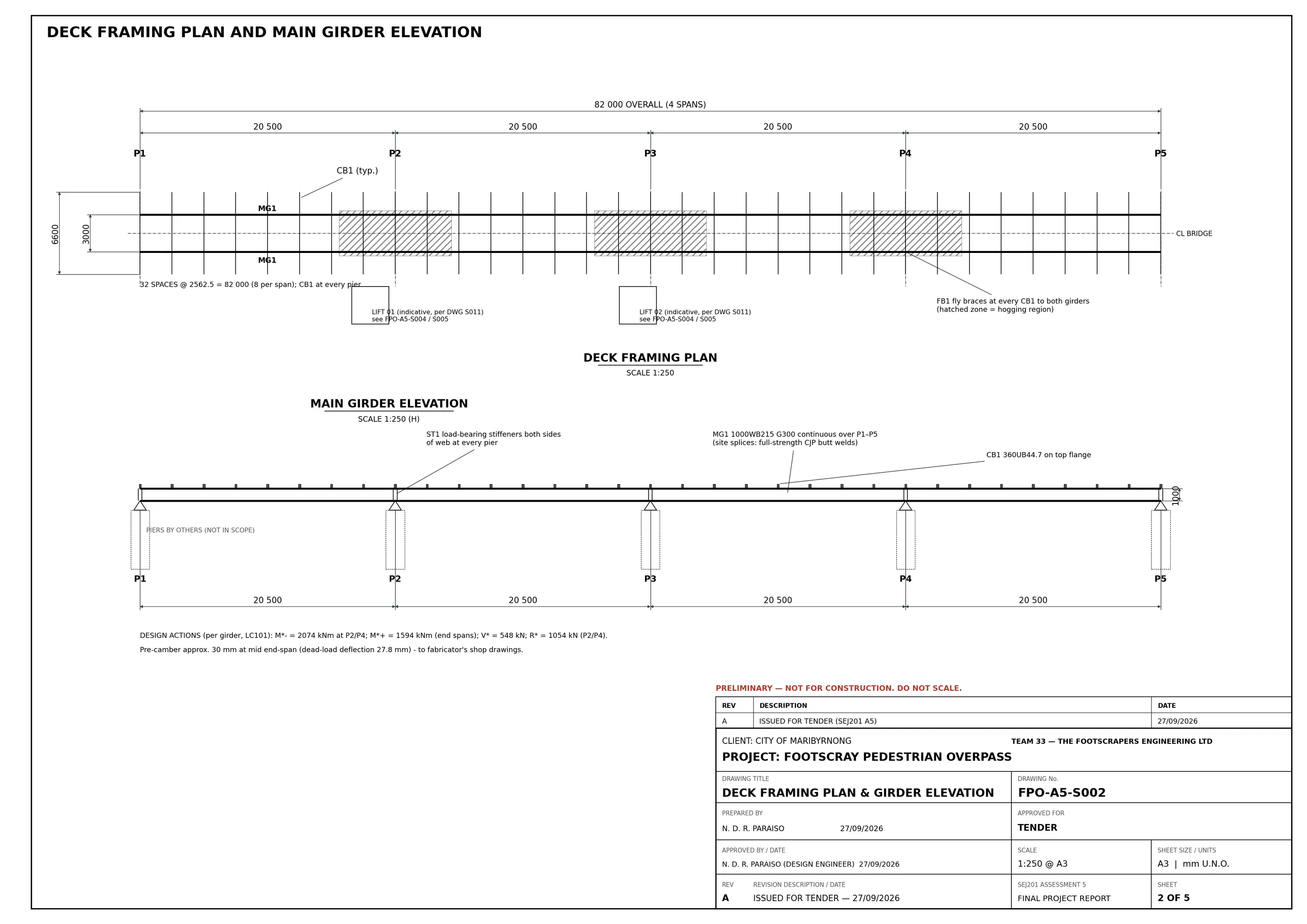
S002 — Deck framing plan & girder elevation 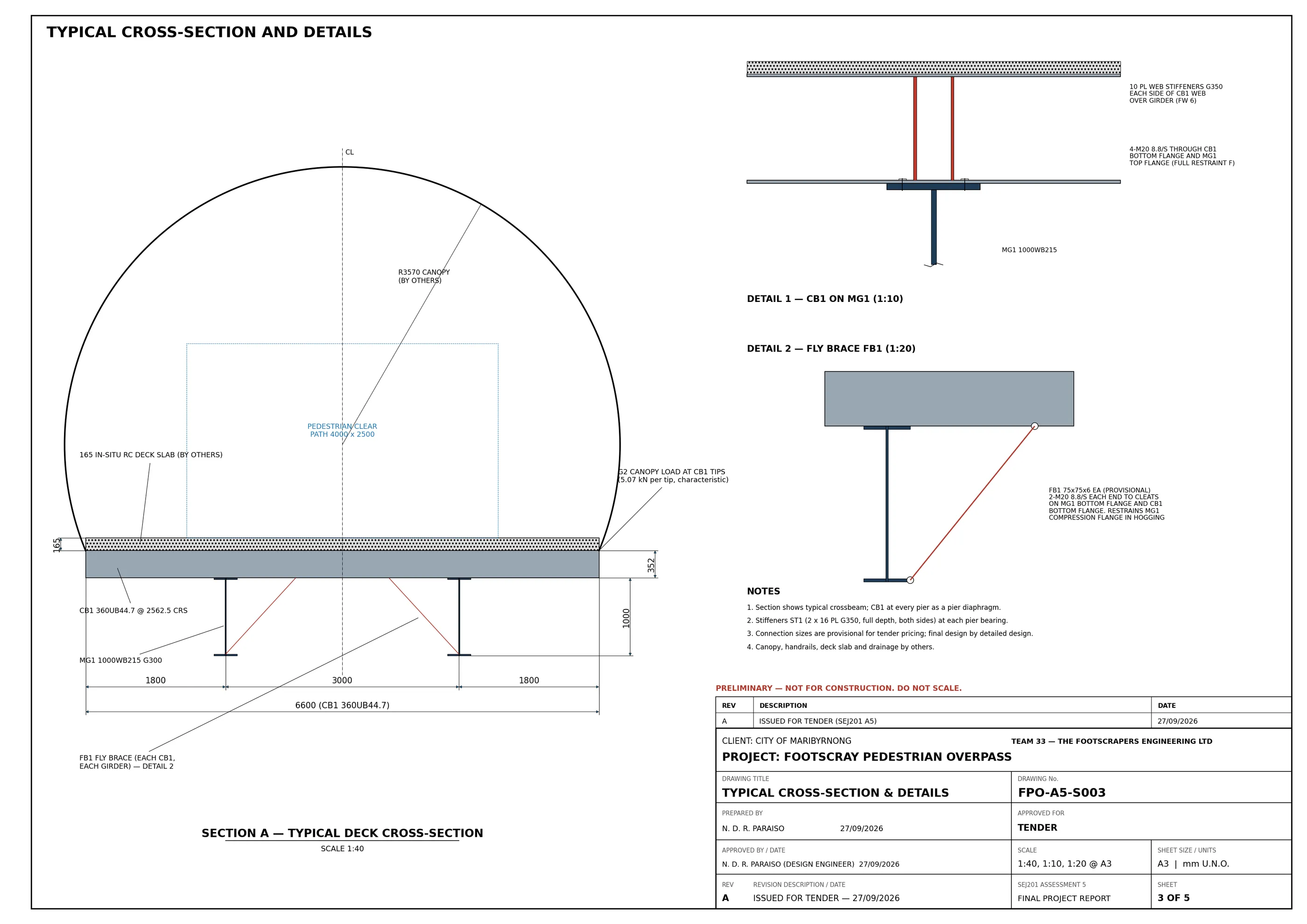
S003 — Typical cross-section & details 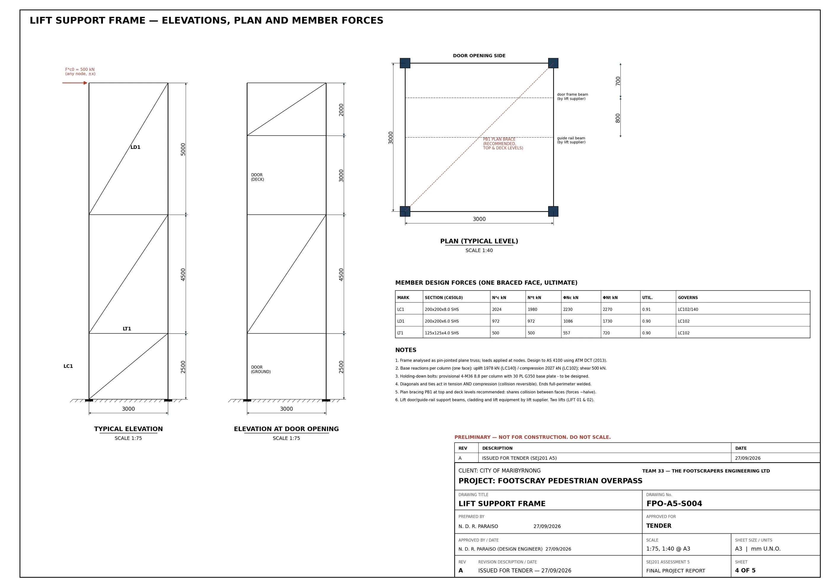
S004 — Lift support frame 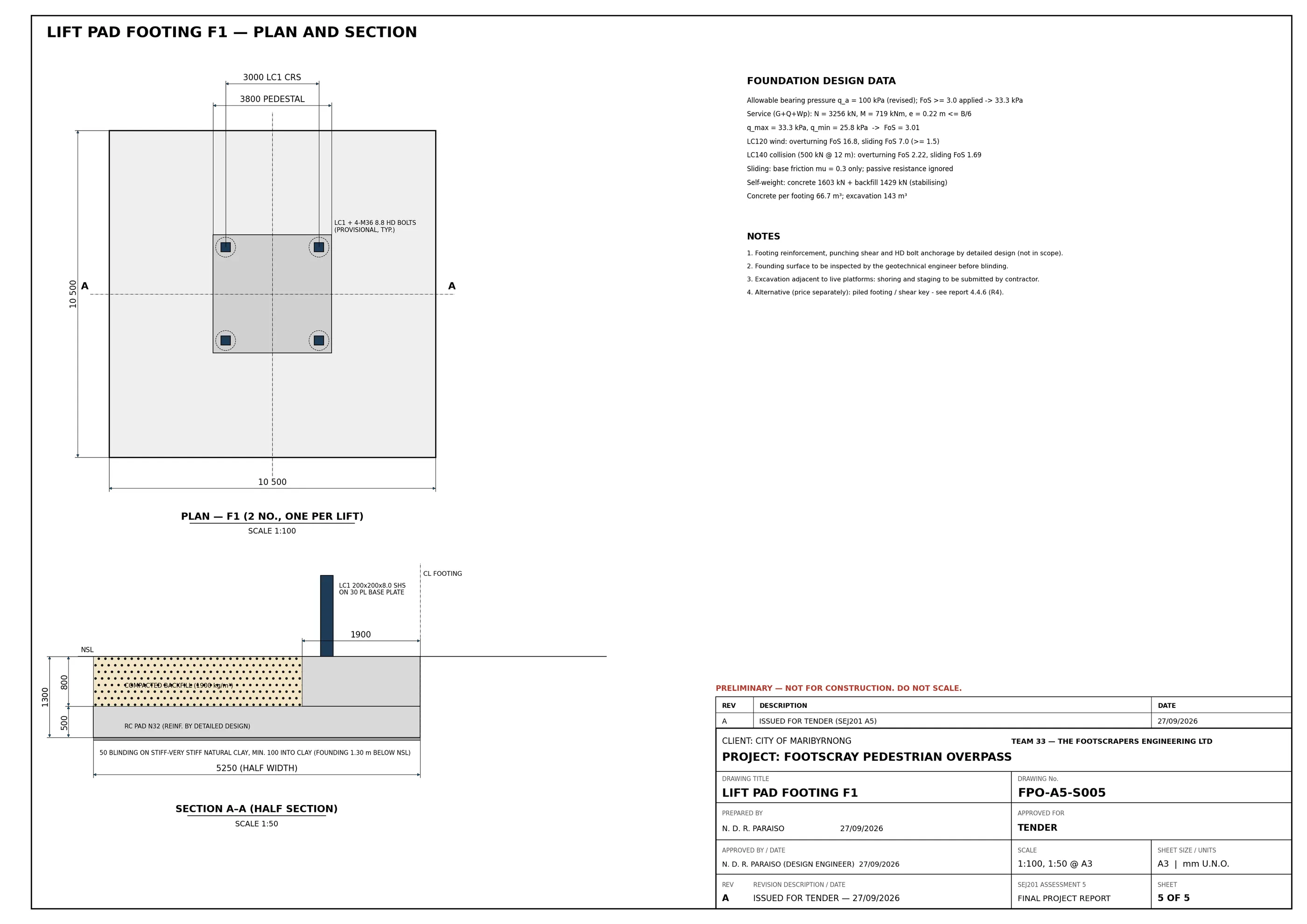
S005 — Lift pad footing F1
09 · Recommendations
What I’d resolve before detailed design
- R1Survey the track centrelines to confirm the 4 m clearance to the 10.5 m footing.The drawings never showed track positions, so this is the biggest open risk.
- R2Confirm how the bearing FoS is applied and where the collision load acts.Could cut the footing to about 8.4 m and shrink the lift frame members considerably.
- R3Add plan bracing at the top and deck levels of the lift frame.Lets two faces share the collision load, so member forces roughly halve.
- R4Price a piled footing (or a shear key) as an alternative.Smaller footprint beside live rail, and it resists the ~2,000 kN column uplift directly.
- R5Analyse the door-opening elevation in 3D.As a pin-jointed truss it can’t carry lateral load in its own plane.
- R6Detail fly braces at every crossbeam and stiffeners at the piers.The girder’s hogging capacity depends on that restraint.
- R7Evaluate 900WB175 Grade 400 girders.About 6.6 t less steel across both girders, if Grade 400 plate is available.
- R8Check pedestrian vibration, connections, base plates and footing reinforcement.Needed to take the design through to construction.
10 · Reflection
Checking equations isn’t checking judgement
“[O]ur checks caught arithmetic and formatting issues but not modelling errors. The wind lever arm in my own footing calculation and the zero-force assumption in the lift truss both passed every reviewer.”
In the group brief my job was the footing, plus proofreading and checking equations. Our team charter had every section checked by three people, and two real modelling errors still got through, one of them mine. The final report was where I went back and fixed them.
What I’d do differently: add a technical checklist to every review, covering a complete free-body diagram, the load path traced to the supports, justified load combinations, and one independent calculation or software check per element. I also want to put ideas forward earlier in planning, rather than mostly reviewing finished work.