Overview
This project took a custom garage creeper from early concepts through to a final CAD model in Autodesk Fusion.
I started by sketching three different concepts, each taking a different approach to the same problem. Each one was drawn as dimensioned views at 1:5 or 1:8 scale, with notes on materials, assembly method and repairability. Between them they explored ergonomics, storage, portability, caster layout, adjustability, and how a creeper could be useful for more than just lying under a car.
Rather than taking one concept straight into CAD, I compared them and combined ideas from Concepts 1 and 3 for the final direction.
Concept development
Concept 1: Adjustable garage creeper
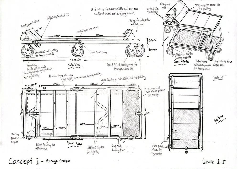
Concept 1 was a fairly traditional creeper layout with extra functionality added: an adjustable headrest, six main caster wheels, wheel brakes, storage space and a raised seating mode for jobs where lying under the vehicle isn’t needed.
I also looked at making parts easier to replace rather than permanently built into the frame, so the design stays practical and serviceable.
Concept 2: One-frame garage creeper
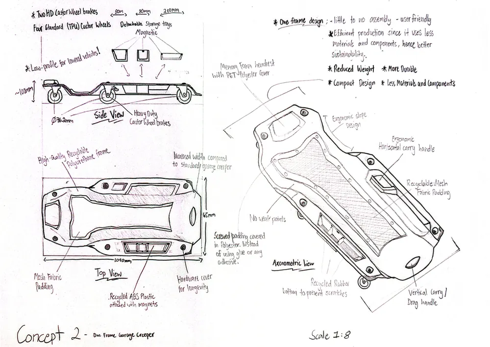
Concept 2 went the other way and focused on a single integrated frame. The aim was fewer separate parts, less weight and easier assembly. It had a low-profile body, shaped padding, detachable storage trays and both horizontal and vertical carry handles.
I also explored recyclable materials and cutting down the material in the frame. It was cleaner and more compact, although it didn’t offer as much flexibility as the other designs.
Concept 3: Three-configuration garage creeper
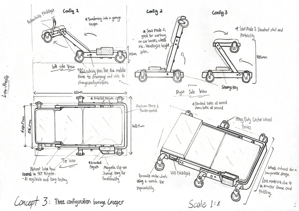
Concept 3 was the most flexible. The idea was a creeper that works in several configurations instead of one fixed position: a normal low-profile creeper, a raised working position, or something closer to a portable workshop stool.
It also had removable caster wheels, magnetic storage, integrated lighting and adjustable frame sections. It was more mechanically complicated than the others, but it introduced a few ideas worth carrying forward.
Design screening
I compared the three concepts using a design-screening process against:
- Functionality
- Ergonomics
- Ease of use
- Manufacturability
- Material use
- Maintainability
- Portability
- Mechanical complexity
No concept won on everything. Concept 1 had the more practical overall layout, while Concept 3 had some of the more interesting ideas around adjustability and function, so I didn’t take either forward unchanged.
Final design direction
The final design is a hybrid. I kept the conventional, practical base layout from Concept 1 and brought across selected features from Concept 3. That gave me a better starting point for CAD without making the design unnecessarily complicated.
The sketches were about exploring ideas, so some dimensions, components and features changed once I started developing the design properly in CAD.
CAD development
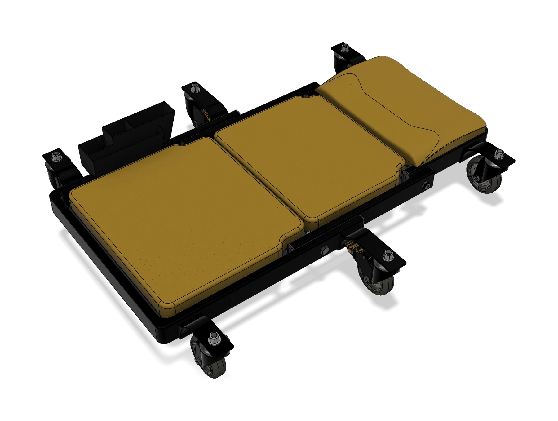
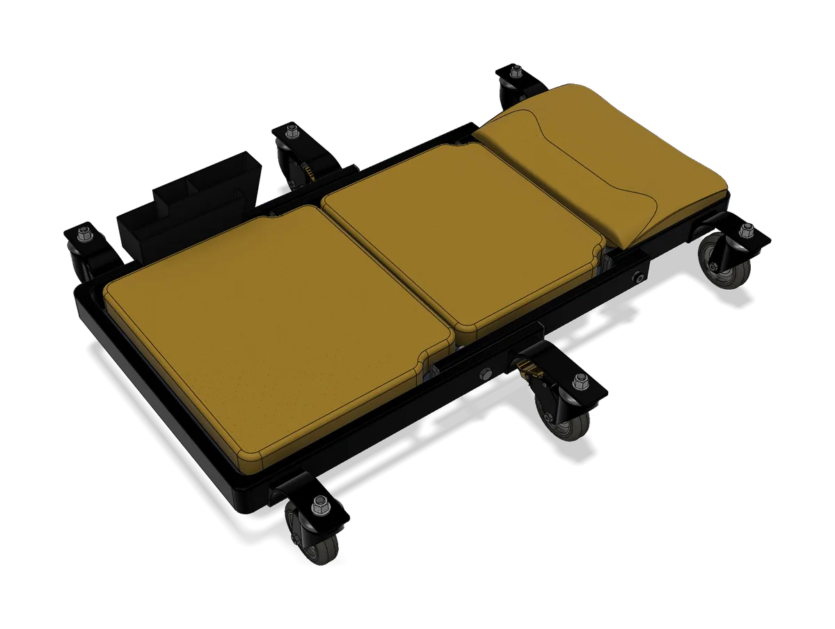
The hybrid was modelled as a full assembly in Autodesk Fusion. This is where I worked through the geometry, component positions, overall proportions and how the parts fit together. Moving from sketches to 3D made it easier to see which ideas worked and which needed simplifying.
The final model has:
- Caster wheels mounted outboard of the frame, with brakes
- A side tray for tools
- Three separate padded sections
- A bolted assembly, so a worn or damaged part can be swapped out without scrapping the whole creeper
The final model is a digital design. It hasn’t been manufactured or tested.
What I learned
- Develop several concepts before committing to one.
- Compare concepts against clear design criteria.
- Combine the strongest features of different concepts.
- Translate hand sketches into a 3D model.
- Think about ergonomics and usability alongside the mechanical design.
- Design parts so they can be maintained or replaced.
- Expect a concept to change once it reaches CAD.
The most interesting concept isn’t always the best one to develop directly. Sometimes the strongest parts of several ideas give a better result.
Next steps
If I kept developing it, the next step would be a proper prototype:
- Structural analysis of the frame
- Final material selection
- Caster, bearing and fastener selection
- Checking clearances under different vehicles
- A more detailed ergonomic evaluation
- Manufacturing drawings
- Building and load-testing a physical prototype, then refining from the results